PDKMaster circuits and layouts for bandgap and ADC
Posted on ma 03 oktober 2022 in NLnet
After a first pure report on analog blocks scalability, I am happy to be able to report on the first PDKMaster based circuits and layouts for the NGI Zero PET funded Analog/Mixed-Signal Library project in this blog post. Reports on the scalability of a bandgap and an ADC circuits were already discussed in a previous blog post. Now for these circuits a PDKMaster based circuit and layout generator have been implemented.
The bandgap implementation contains first version of code that does the sizing of the transistors targeting minimum power consumption of the bandgap. The ADC implenentation allows to quickly configure and generate a circuit and layout for an SAR ADC from 1 to 8 number of bits.
Voltage reference (e.g. bandgap)
Based on the bandgap report a first implementation has been made using the PDKMaster framework for a circuit and corresponding layout generation. A notebook is used to generate these blocks; the output of the full run can be found in the bandgap notebook.
The ciruit and layout generation code can be found in c4m.pdk.sky130.bandgap The classes in this module are Bandgap and BandgapCell.
Bandgap objects are only capable of circuit generation and simulation but no layout. It is using continuous values for dimensions able to violate grid DRC rules etc. A first version for the computation of an optimized version of a bandgap is implemented in the compute_minpower() method of the class. The target is to minimize the power consumed by the bandgap. This method thus shows how the simulation support in PDKMaster can be used in optimization.
BandgapCell objects on the other hand represent a circuit with corresponding layout with dimensions of the structures that need to conform to the DRC rules. With the convert2cell() method a Bandgap object can be converted to a BandgapCell one. As this is the first version of the class this separation in two classes may in the future be removed before a general bandgap structure is upstreamed in a more generalized library.
In the bandgap notebook one can see how this all is applied to three different bandgap versions, one with 5V devices; one with low-Vt 1.8V devices and one with regular Vt 1.8V devices. First compute_minpower() is called and then converted to a cell with layout using convert2cell(). Normally the resulting reference voltage should be around 1.2V but one can see that for the versions with 1.8V devices - even the low-Vt ones - this value is not reached. This means that the Vt of these devices is too high relative to the supply voltage to give enough operation margin for the current mirror to work in saturation.
Although the compute_minpower() seems to be able to compute a bandgap for the three different varations of transistors it's also the first version that has room for improvement. In good open source fashion this means that the code is open for improvements or even for other stategies other than minimum power for computing the bandgap transistor dimensions.
ADC
For the ADC it's corresponding report was used as guidance. The choice was made to implement a single-ended ADC using the pre-amplifier and the Lewis and Gray comparator as discussed in the document. The digital logic in the sequencer has been changed slightly to better map to the cells available in the c4m-flexcell library; more detail is available as comment in the code. The simulation results in the notebook run shows that the adapted sequencer works as expected.
In this case using nominal value transistors for most of the transistors gave results that was fast enough for a first version. So the focus in this excercise was more on easy configuration of the number of bits for the ADC rather than on deriving an optimized version. From the notebook run one can see the results of running the ADC generation for both an 8 bit and a 6 bit version and it also results in a gds file with 2 ADCs in it.
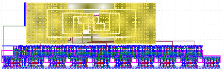
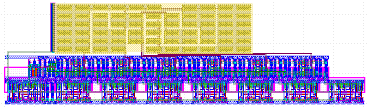
Above are the 8bit ADC on the left and the 6bit version on the right. At the top of the cell are capacitors and one can see the need for more capacitors for the 8bit ADC.
This shows the flexibility in configuration of the number of bits for the ADC based on the flexibility of the PDKMaster framework. In more classical approaches for analog design a 6 bit version and a 8 bit version of an ADC would involve quite some more work in schematic capture and layout generation.
As also said in the notebook the use of PMOS switch to capture the input voltage limits the input range of the ADC. This value will be further investigated when an ADC will be put on a real tape-out.
For ADC the code has been done in one class named ADC in a file ADC_support.py local to the notebook. c4m-pdk-sky130 issue 4 has been filed to move the ADC code into c4m.pdk.sky130.
Simulation and layout support code
For the simulations done for the bandgap some simulation support code has been provided in c4m.pdk.sky130._simulation. This contains things like Ids vs Vgs simulation, result plotting support code etc. This is thus more general code where at least part of it could be ripe for upstreaming; PDKMaster issue 26 has been created to track this.
For the layout generation of both the bandgap and the ADC some common layout support code has been used. It is available in c4m.pdk.sky130._layout. Currently a class Sky130Layout is defined which is higher level layout generation code using class CircuitLayouter from PDKMaster internally. PDKMaster issue 25 has been filed for upstreaming the code.
Under construction
The code for these two blocks still lives in the dev branch with complicated inter-project dependencies when writing this code. A branch named blog20221003 has been made on the related repos that should be consistent. So if one wants to reproduce the generation of the block one needs to checkout this branch for the PDKMaster, c4m-flexcell, c4m-flexio, c4m-flexmem and the c4m-pdk-sly130 repos. Don't hesitate to contact me through one of the links on the left side if you want to try this yourself.
Alternative is to wait until the layout generation code is upstreamed and the circuit and layout generation live in the main branch(es) of the repo. After completion of the PDKMaster v0.9.0 milestone - which is still planned for this month - things should become more fit for external use and external contributions.