Fixing the ESD generator
Posted on zo 01 november 2020 in NLnet
This is a continuation on my previous blog on first tests on the ESD generator.
Problems
After some more debugging the voltage multiplier of the ESD Generator has been made to work. Detailed simulation results of the problems can be found in this Jupyter notebook in the created sim folder in the ESD Generator source folder. Summary of the problems:
- Leakage problem reported on in the previous blog post is mainly caused by the 10MΩ input impedance on the oscilloscope input not the diode leakage current
- The bridge rectifier in the design is not needed and actually blocks the proper working of the voltage multiplier.
- A DC offset is only seen in between the odd or the even nodes in the voltage multiplier.
Measurement results
In order to increase the input impedance and to allow to measure the higher generated voltages I used a voltage divieder to mimic 100:1 probe. A 1GΩ resistor was put in series with the probe. Combined with the 10MΩ input impedance of the oscilloscope this gives 100:1 ratio plus it increases the resistance on the measurement points from 10MΩ to 1GΩ.
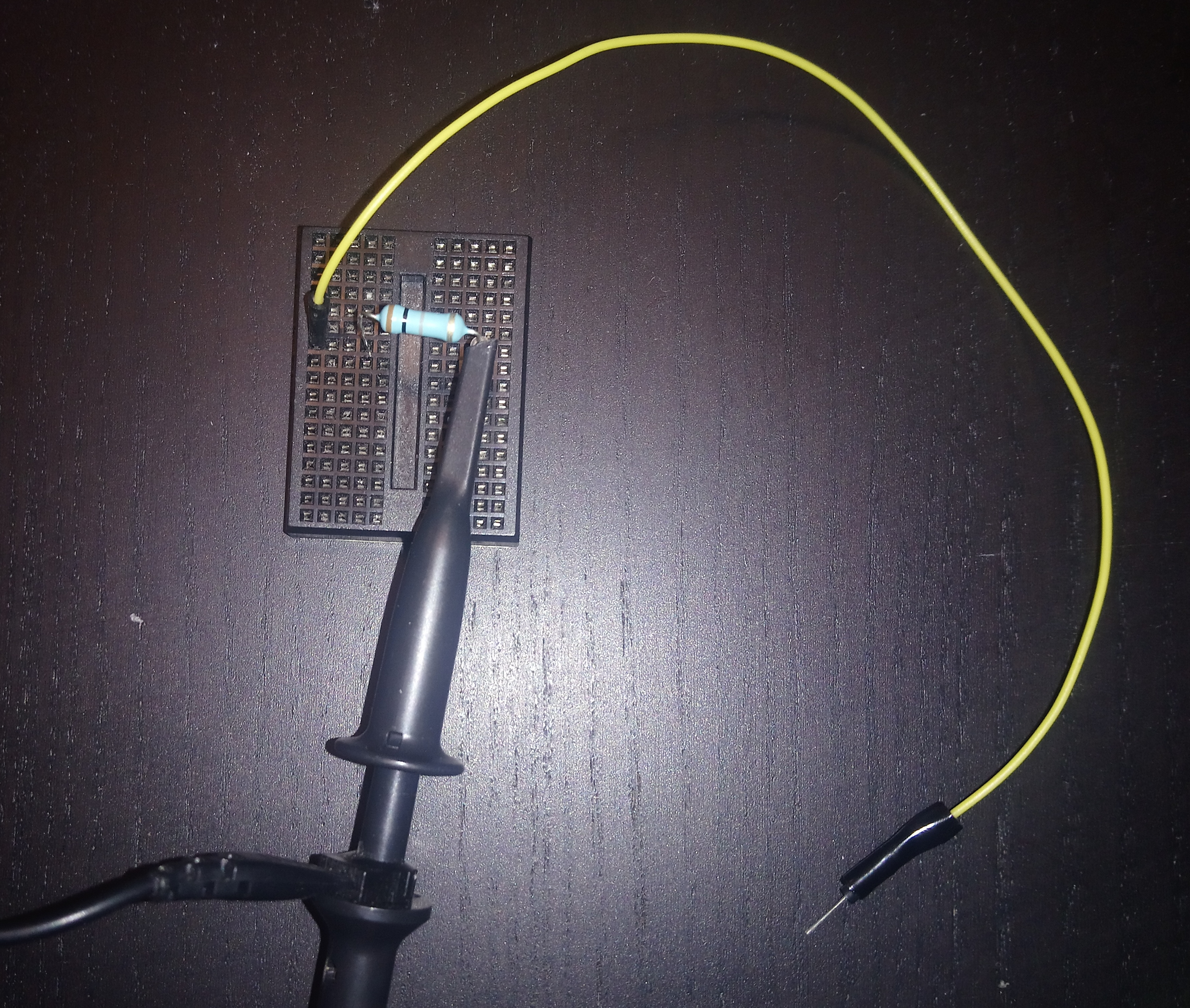
To solve the problems as identified in the previous paragraph the diodes on the design have been desoldered and the output of the transformer directly connected to the input of the voltage multiplier. Now I can see the voltage multiplier working as it should. In the next oscilloscope measurements I have given the voltage on node 2 to 6 on the voltage multiplier:
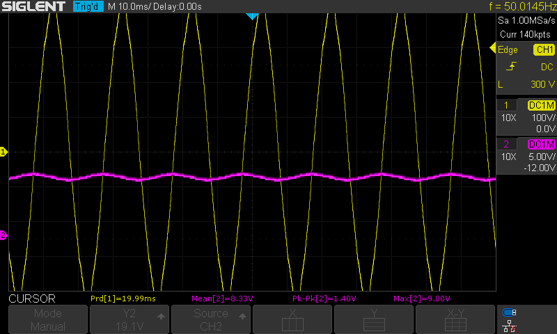
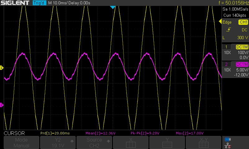
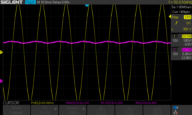
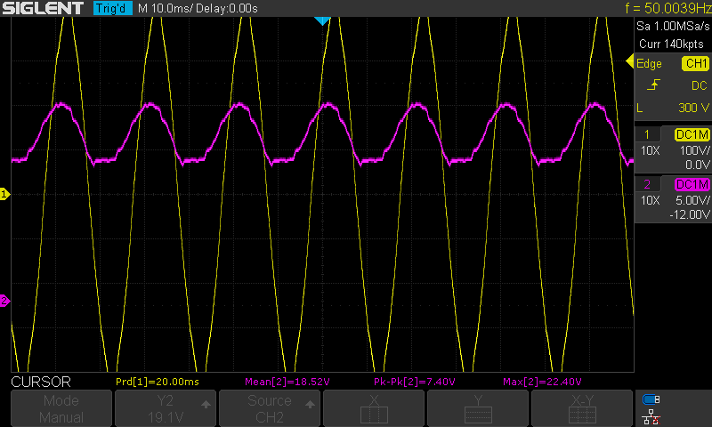
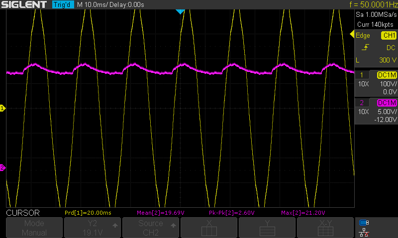
The voltages for channel two (purple) are using the 100:1 probing so they have to be multiplied by 100 to get the actual value. We can clearly see the difference in behaviour between odd and even nodes. The measured mean voltage on the even nodes is summarized in the next table:
| Node | Avg. voltage |
|---|---|
| n2 | 830 V |
| n4 | 1610 V |
| n6 | 1970 V |
For the first nodes a capacitance of 4.7nF was used and for the last two nodes the 150pF of the original design was used. One can clearly see that for the latter ones the load of the diode leakage and the 1GΩ reduced the voltage step achieved significantly together with bigger ripple on the output.
ESDGenerator v0.2 plans
So these are the plans for a revision of the ESD Generator:
- Remove bridge rectifier
- Increase the charge pump capacitors capacitance to reduce ripple
- I have also ideas to provide the necessary connections on the board so different voltage multipliers could be chained together to generate even higher voltages.